ESP32 OLED Drawing Pad V1
Project Overview
The ESP32 OLED Drawing Pad teaches advanced techniques for creating interactive graphics applications with wireless control using I2C display communication and WiFi connectivity.
This project creates a real-time drawing application on a 128×64 SSD1306 OLED display controlled remotely through a web browser interface on any connected device. Users can draw freehand artwork, control cursor movement, adjust brush size, and clear the display using an intuitive web-based drawing canvas interface.
When you run the project, the ESP32 creates an access point that broadcasts a WiFi network accessible from mobile phones or computers. Users connect to the web interface and draw on a 320×160 canvas which maps to the 128×64 OLED display showing real-time pixel rendering.
Key Features: I2C communication between ESP32 and OLED displays, WiFi access point hosting embedded web server, WebSocket protocol for real-time command transmission, pixel buffer management with efficient bit-packing storage, Bresenham line drawing algorithm with adjustable brush thickness, responsive web interface with live preview display, lightweight code optimized for microcontroller platforms.
Components Required
To build this project, collect these specific items from your kit and ensure each component is in good working condition.
ESP32 Development Board x 1, SSD1306 OLED Display (128×64) x 1, Breadboard x 1, Jumper Wires x 4, USB Cable x 1.
Circuit Connections
Step 1: Connect Ground Rail for Shared Reference
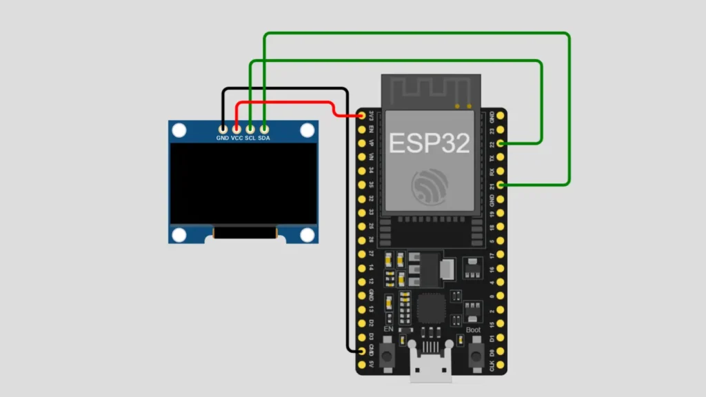
Connect the ESP32 GND ground pin directly to the negative rail of your breadboard to establish a shared ground connection for your entire circuit and all connected electronic components throughout the system.
Step 2: Place and Position OLED Display Module
Position the SSD1306 OLED display module carefully near the top edge of your breadboard for convenient access and proper alignment with all jumper wire connections during the assembly process to ensure success.
Step 3: Connect VCC Power Pin to Supply
Connect the OLED VCC power pin directly to the ESP32 3.3V output pin to provide the correct voltage level and adequate power supply for the small OLED display module operation and functionality.
Step 4: Connect Ground Pin for Return Path
Connect the OLED GND ground pin to the breadboard negative rail to complete the power circuit and establish the electrical return path for all current flowing through connected components on the breadboard.
Step 5: Connect SDA Data Pin for I2C
Connect the OLED SDA serial data pin to ESP32 GPIO pin 21 to enable I2C protocol serial data transmission between the ESP32 microcontroller and the OLED display device communication successfully.
Step 6: Connect SCL Clock Pin for Timing
Connect the OLED SCL serial clock pin to ESP32 GPIO pin 22 to provide I2C timing synchronization that coordinates precise data transmission between all connected I2C devices on the bus system.
Step 7: Verify All Connections Before Upload
Double-check all four display pins for correct connections and secure jumper wire placement before uploading any code to your ESP32 microcontroller board to prevent connectivity problems during operation and testing.
Important: The SSD1306 OLED display uses the I2C protocol, a two-wire communication standard where the SDA pin transmits data and the SCL pin provides essential timing synchronization for reliable data transfer.
Software Requirements
Before uploading code to your ESP32, install the following software components, libraries, and drivers on your development system.
Arduino IDE : Download and install the latest version from the official Arduino website for code development, editing, and uploading to your microcontroller board.
ESP32 Board Package : Add the ESP32 board package to Arduino IDE by accessing Boards Manager and searching for ESP32 with proper version selection.
Adafruit GFX Library : Install this library using Arduino IDE Library Manager to access graphics drawing functions and text rendering capabilities for display output.
Adafruit SSD1306 Library : Install this library for complete SSD1306 OLED display control, initialization, and I2C communication protocol implementation.
CH340 USB Driver : Download and install the CH340 USB driver for your specific operating system to enable ESP32 board serial communication with your computer.
Verify Installation : Open Arduino IDE, select your ESP32 board from Tools menu, and confirm the COM port shows your connected microcontroller device.
How the Project Code Works
Initialize Display and WiFi Access Point Configuration
The setup function configures the SSD1306 OLED display with I2C communication at GPIO pins 21 and 22 for reliable data transmission. The ESP32 creates a WiFi access point allowing nearby devices to connect wirelessly without requiring existing network infrastructure or router.
Setup Pixel Buffer System and Drawing Functions
The project uses a 1024-byte bit-packed pixel buffer storing 128×64 pixels efficiently using one bit per pixel for monochrome display. Helper functions setPixel, clearPixel, and getPixel manage individual pixel states while drawThickLine implements the Bresenham algorithm for smooth line rendering with variable brush thickness.
Implement WebSocket Communication Protocol Handler
The WebSocket server receives drawing commands transmitted from the web interface in real-time through persistent bidirectional communication. The onWsEvent function parses drawing commands including line coordinates and brush radius then maps canvas coordinates from 320×160 to 128×64 display dimensions.
Process and Map Drawing Commands from Web Interface
Commands received from the web browser are parsed and scaled to match OLED display resolution automatically adjusting coordinates and brush size. The drawing coordinates from the larger web canvas are mapped proportionally to the smaller OLED display ensuring accurate representation of user drawings.
Render Graphics and Update OLED Display Buffer
The flushToOLED function reads the pixel buffer and renders each active pixel to the OLED display using the Adafruit GFX library drawing functions. The embedded web page includes HTML canvas for user drawing with JavaScript handling touch and mouse input events sending commands via WebSocket.
Expected Output
After uploading your code to the ESP32, connect the USB cable and power on the development board.
The OLED display shows connection information directing users to access the web interface at the access point IP address. Users connect their phone or computer to the WiFi network named OLED-Draw and open the browser to access the interactive drawing interface.
The web interface displays a live preview of the OLED content alongside a larger drawing canvas allowing real-time visualization of artwork. Users can draw freehand, adjust brush size with a slider, and clear the display with a button while seeing updates on the OLED instantly.
Operational Troubleshooting
OLED Display Remains Blank or Unresponsive to Code :- Verify all four display pins connect to correct ESP32 GPIO pins as specified in the circuit diagram. Check VCC and GND connections for proper power supply with adequate current. Confirm the USB cable provides sufficient power and verify the I2C address matches your OLED model.
WiFi Access Point Does Not Appear or Web Interface Not Accessible :- Verify the WiFi setup code is executing by checking serial monitor output for connection messages. Check that your device is searching for and attempting to connect to the OLED-Draw network name. Try restarting the ESP32 board by pressing the reset button and waiting for the startup sequence to complete.
Drawing Commands Received But Not Rendering on OLED Display :- Confirm both Adafruit GFX and SSD1306 libraries are correctly installed in your Arduino IDE folder. Verify the flushToOLED function is being called to update the display after each drawing operation. Check I2C communication stability and confirm the pixel buffer is being populated with drawing data.
Web Canvas Draws But OLED Display Shows Corrupted or Partial Graphics :- Ensure all jumper wire connections are secure with no loose contacts interrupting data transmission between devices. Verify the coordinate mapping calculation correctly scales from 320×160 canvas to 128×64 display resolution. Check that the pixel buffer is large enough to store all data without overflow or memory corruption.
What You Learned
By finishing this project, you understand how to create interactive applications with WiFi connectivity and real-time data transmission using WebSocket communication protocols. You have learned techniques for managing pixel buffers, implementing line drawing algorithms, and mapping coordinate systems between different resolutions on microcontroller systems.
You can apply web server technologies to create remote control interfaces for embedded devices and sensors. You have experienced how to combine hardware display control with wireless network capabilities to create sophisticated interactive applications on resource-constrained microcontroller platforms.
WHAT'S NEXT?
Ready to Build More?
Explore more Lifetronix projects, improve your skills, and turn your ideas into real working prototypes.