ESP32 Wi-Fi RGB Controller V2
Project Overview
The ESP32 WiFi RGB Controller V2 teaches advanced techniques for creating professional IoT applications with enhanced user interfaces and additional hardware control features using web dashboards and real-time PWM signals.
This project provides wireless control of an RGB LED through an improved modern web-based dashboard accessible from phones or computers on the same WiFi network. Users adjust independent red, green, and blue channel sliders in real-time while viewing live HEX color values and accessing six quick color presets with an additional one-click output shutdown feature.
When you run the project, the ESP32 connects to an existing WiFi network and hosts a refined responsive web server with professional color control interface. The enhanced dashboard sends color commands and control signals to the ESP32 which converts them to precise PWM signals managing RGB LED brightness across all channels with improved responsiveness.
Key Features: WiFi connectivity to existing networks without access point creation, professional HTML5 web dashboard with modern styling and animations, independent PWM control of red green and blue channels with 8-bit precision, six quick color presets including pure colors and specialty palettes, one-click RGB output shutdown for complete LED control, live HEX color display with dynamic real-time visualization, mobile-friendly responsive design, lightweight code optimized for microcontroller platforms.
Components Required
To build this project, collect these specific items from your kit and ensure each component is in good working condition.
ESP32 Development Board x 1, RGB LED (common cathode) x 1, Current-Limiting Resistors x 3, Breadboard x 1, Jumper Wires x 4, USB Cable x 1.
Circuit Connections
Step 1: Connect Ground Rail for Shared Reference
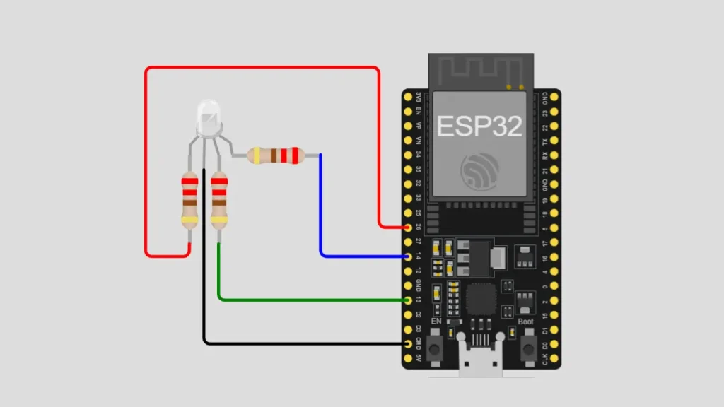
Connect the ESP32 GND ground pin directly to the negative rail of your breadboard to establish a shared ground connection for your entire circuit and all connected electronic components throughout the system.
Step 2: Place RGB LED Module on Breadboard
Position the RGB LED carefully on your breadboard ensuring proper spacing from other components for convenient access and safe wiring. The longest pin of the RGB LED is the common cathode which connects to ground through a resistor path.
Step 3: Connect Red Channel with Current-Limiting Resistor
Insert a current-limiting resistor between the RGB LED red pin and a new breadboard row then connect this row to ESP32 GPIO pin 26 for PWM red channel control.
Step 4: Connect Green Channel with Current-Limiting Resistor
Insert a current-limiting resistor between the RGB LED green pin and a separate breadboard row then connect this row to ESP32 GPIO Pin 13 for PWM green channel control.
Step 5: Connect Blue Channel with Current-Limiting Resistor
Insert a current-limiting resistor between the RGB LED blue pin and another breadboard row then connect this row to ESP32 GPIO pin 14 for PWM blue channel control.
Step 6: Connect RGB LED Common Cathode to Ground
Connect the RGB LED common cathode (longest pin) through the final resistor to the breadboard ground rail completing the current return path for all color channels.
Step 7: Verify All Connections Before Upload
Double-check all resistor values for appropriate current limiting and verify all GPIO pin connections match the code configuration. Confirm LED polarity with the longest pin as common cathode and test connections with a multimeter before uploading code.
Important: RGB LEDs require current-limiting resistors on each channel to prevent damage. Use appropriate resistor values typically 220-330 ohms depending on LED brightness requirements and current availability from the ESP32.
Software Requirements
Before uploading code to your ESP32, install the following software components, libraries, and drivers on your development system.
Arduino IDE : Download and install the latest version from the official Arduino website for code development, editing, and uploading to your microcontroller board.
ESP32 Board Package : Add the ESP32 board package to Arduino IDE by accessing Boards Manager and searching for ESP32 with proper version selection.
WiFi Library : This library comes built-in with the ESP32 Board Package providing WiFi connection and network management capabilities for wireless networking.
WebServer Library : This library comes built-in with the ESP32 Board Package enabling HTTP server functionality for hosting web interfaces on the microcontroller. implementation.
CH340 USB Driver : Download and install the CH340 USB driver for your specific operating system to enable ESP32 board serial communication with your computer.
Verify Installation : Open Arduino IDE, select your ESP32 board from Tools menu, and confirm the COM port shows your connected microcontroller device.
How the Project Code Works
Initialize WiFi Connection and Enhanced Web Server Setup
The setup function configures ESP32 GPIO pins 26, 13, and 14 as PWM output pins with 8-bit resolution supporting values from 0 to 255. The ESP32 connects to a predefined WiFi network using stored credentials then initializes the enhanced WebServer with improved routing.
Configure Advanced PWM Channels and Output Control
The PWM initialization configures each RGB channel with appropriate frequency and resolution for smooth color transitions without flickering effects. The output control system manages a shutdown state variable that disables all PWM signals when activated allowing complete LED control.
Implement Enhanced HTTP Handlers with Additional Endpoints
The web server includes handler functions for processing GET requests including setRGB for color control and shutdown for output management. The handleRoot function serves an improved HTML page with professional styling while handleSetRGB and handleShutdown process control requests.
Parse RGB Values and Implement Shutdown Logic
The RGB values extracted from HTTP requests are validated for range between 0 and 255 then mapped to PWM duty cycle values. The shutdown handler sets a control flag preventing PWM signals while maintaining state information for proper response handling.
Generate Professional Dashboard with Enhanced Interface
The embedded HTML page includes improved JavaScript with better event handling and animations for sliders and color visualization. The web interface displays six preset buttons, live RGB values, HEX color codes, and a prominent shutdown button with visual feedback.
Expected Output
After uploading your code to the ESP32, open the Serial Monitor at 115200 baud and observe the connection status messages displayed.
The RGB LED powers on displaying the initial color configuration while the ESP32 connects to WiFi and prints its local IP address. Copy the IP address from Serial Monitor and open it in a browser on any device connected to the same WiFi network.
The professional web dashboard displays interactive sliders for each RGB channel, a live color preview with animations, HEX value display, six preset buttons, and a shutdown button. Adjusting any slider immediately changes the LED color in real-time while the shutdown button disables all output with a single click.
Operational Troubleshooting
RGB LED Remains Off or One Color Channel Does Not Light :- Verify the RGB LED polarity with the longest pin as common cathode connected to ground. Check that current-limiting resistors are present on each color channel and measure resistance values with a multimeter. Test LED continuity and confirm GPIO pins 26, 13, and 14 have secure connections without loose wires.
ESP32 Fails to Connect to Wi-Fi or No IP Address Appears in Serial Monitor :- Verify the Wi-Fi network name and password in the code match your actual wireless network credentials exactly including capitalization. Check that your Wi-Fi network is broadcasting and within range of the ESP32 board. Restart the ESP32 using the reset button and monitor Serial output for connection status updates.
Sliders Do Not Change LED Colors or Shutdown Button Does Not Work :- Ensure both the ESP32 and your device are connected to the same Wi-Fi network without using separate networks. Verify the IP address copied from Serial Monitor is correct and try refreshing the browser page multiple times. Check that the WebServer is running by monitoring Serial output for HTTP request logs from the dashboard.
Color Changes Work But Shutdown Button Does Not Disable Output or Output Remains On :- Confirm the shutdown handler properly sets the control flag and that the PWM update functions check this flag before outputting signals. Verify the GPIO pins remain configured for PWM output and that analogWrite calls are being skipped when shutdown is activated. Test the shutdown logic by checking Serial output for handler invocation messages.
What You Learned
By finishing this project, you understand how to create professional IoT applications with enhanced user interfaces combining WiFi connectivity and sophisticated hardware control. You have learned techniques for implementing multi-function web dashboards, managing complex control logic, and providing intuitive user interfaces for remote device operation.
You can apply advanced web interface design and multi-endpoint server architecture to create production-grade IoT applications on microcontroller platforms. You have experienced how professional dashboard design with clear visual feedback improves user experience and control precision on embedded systems.
WHAT'S NEXT?
Ready to Build More?
Explore more Lifetronix projects, improve your skills, and turn your ideas into real working prototypes.