ESP32 Smart Battery Dashboard V1
Project Overview
The ESP32 WiFi Battery Monitor teaches advanced techniques for creating real-time battery monitoring applications with animated web dashboards using ADC voltage reading and WiFi connectivity.
This project monitors battery voltage levels and charging status wirelessly through a modern web dashboard accessible from phones or computers on the same WiFi network. The system displays live battery percentage with animated charging indicators, wave animations, and status information updated in real-time with smooth visual transitions.
When you run the project, the ESP32 reads battery voltage through an analog input pin and charging status through a digital detection pin while connecting to WiFi. The web interface displays an animated battery icon that fills as the battery charges with wave effects and live voltage readouts showing percentage, voltage, and charging status.
Key Features: WiFi connectivity to existing networks without access point creation, real-time battery voltage monitoring through ADC analog input pins, charging status detection with configurable thresholds, animated battery icon with charging wave effects, live battery percentage and voltage display, dark-themed responsive web dashboard, JSON data transmission for live updates, mobile-friendly interface adapting to any screen size, lightweight code optimized for microcontroller platforms.
Components Required
To build this project, collect these specific items from your kit and ensure each component is in good working condition.
ESP32 Development Board x 1, Battery Cell or Power Supply x 1, Voltage Divider Resistors (2kΩ and 1kΩ) x 1, Charger Module or Detection Circuit x 1, Breadboard x 1, Jumper Wires x 4, USB Cable x 1.
Circuit Connections
Step 1: Connect Ground Rail for Shared Reference
Connect the ESP32 GND ground pin directly to the negative rail of your breadboard to establish a shared ground connection for your entire circuit and all connected electronic components throughout the system.
Step 2: Create Voltage Divider for Battery Monitoring
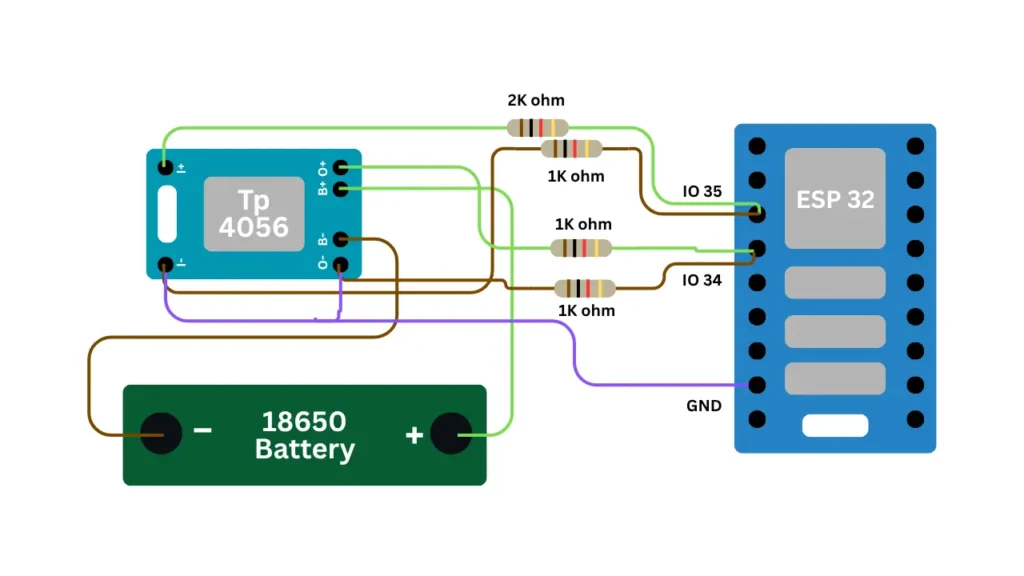
Build a voltage divider using a 2kΩ resistor in series with a 1kΩ resistor connecting the battery positive terminal through both resistors to ground. The junction between resistors connects to ESP32 GPIO pin 34 for battery voltage measurement through the ADC.
Step 3: Connect Battery Positive to Voltage Divider Input
Connect the positive terminal of your battery or power supply to the first resistor in the voltage divider circuit. This allows the ADC pin to read a scaled-down voltage safe for the microcontroller while maintaining accurate battery monitoring.
Step 4: Connect Voltage Divider Ground Reference
Connect the ESP32 GND ground pin directly to the negative rail of your breadboard to establish a shared ground connection for your entire circuit and all connected electronic components throughout the system.
Step 5: Connect Charger Detection to GPIO Pin
Connect a charging detection circuit output to ESP32 GPIO pin 35 for monitoring charging status and state. Use a simple comparator circuit or charging module output that provides a digital signal indicating whether the charger is connected.
Step 6: Configure Battery Connection Safety
Ensure the battery or power supply is properly rated for your monitoring circuit and includes appropriate protection. Verify all connections are secure and no exposed wire ends could cause short circuits or damage.
Step 7: Verify All Connections Before Upload
Double-check all resistor values in the voltage divider for accurate scaling and verify GPIO pin connections match the code configuration. Test continuity with a multimeter and confirm voltage at the ADC pin falls within safe operating range before uploading code.
Important: Voltage dividers must scale battery voltage to safe levels for ESP32 ADC input pins which accept maximum 3.3V. The 2kΩ to 1kΩ ratio provides appropriate scaling for typical battery monitoring applications ensuring accurate readings.
Software Requirements
Before uploading code to your ESP32, install the following software components, libraries, and drivers on your development system.
Arduino IDE : Download and install the latest version from the official Arduino website for code development, editing, and uploading to your microcontroller board.
ESP32 Board Package : Add the ESP32 board package to Arduino IDE by accessing Boards Manager and searching for ESP32 with proper version selection.
WiFi Library : This library comes built-in with the ESP32 Board Package providing WiFi connection and network management capabilities for wireless networking.
WebServer Library : This library comes built-in with the ESP32 Board Package enabling HTTP server functionality for hosting web interfaces on the microcontroller. implementation.
CH340 USB Driver : Download and install the CH340 USB driver for your specific operating system to enable ESP32 board serial communication with your computer.
Verify Installation : Open Arduino IDE, select your ESP32 board from Tools menu, and confirm the COM port shows your connected microcontroller device.
How the Project Code Works
Initialize WiFi Connection and ADC Battery Monitoring Setup
The setup function configures ESP32 GPIO pin 34 as an analog input for battery voltage measurement and GPIO pin 35 for charging detection. The WiFi connection is established using stored credentials while the WebServer initializes on port 80 for dashboard hosting.
Configure ADC Sampling and Voltage Calculation Parameters
The battery monitoring system averages multiple ADC samples for noise reduction and smoothing using exponential filtering on voltage readings. Constants define the battery divider ratio, sample count, and voltage thresholds for charging status detection.
Implement HTTP Handlers for Battery Data Requests
The web server includes handler functions for serving the dashboard HTML page and processing JSON data requests from the browser. The handleData function formats battery voltage, percentage, and charging status as JSON for real-time dashboard updates.
Calculate Battery Percentage from Voltage Readings
The voltage to percentage conversion uses calibration points mapping minimum voltage to 0 percent and maximum voltage to 100 percent. The charging status detection compares charging pin voltage against configurable thresholds to determine charging or full states.
Generate Animated Dashboard with Real-Time Display Updates
The embedded HTML page includes animated SVG battery icon elements that fill with color as percentage increases and wave animations that activate during charging. JavaScript handles periodic data requests and smooth animations creating an engaging user experience.
Expected Output
After uploading your code to the ESP32, open the Serial Monitor at 115200 baud and observe the connection status messages displayed.
The ESP32 connects to WiFi and displays its local IP address while continuously monitoring battery voltage through the ADC pin. Copy the IP address from Serial Monitor and open it in a browser on any device connected to the same WiFi network.
The animated web dashboard displays a battery icon that fills progressively as battery charge increases with live voltage readings and percentage display. The charging indicator shows wave animations when charging is detected and updates all values in real-time every 500 milliseconds.
Operational Troubleshooting
Battery Voltage Readings Appear Incorrect or Percentage Does Not Match :- Verify the voltage divider resistor values match the 2kΩ to 1kΩ configuration in the code calculations. Check that the battery divider ratio constant is correctly set in code to match your physical resistor values. Test the ADC voltage at GPIO pin 34 with a multimeter to confirm proper scaling from your battery voltage.
ESP32 Fails to Connect to Wi-Fi or No IP Address Appears in Serial Monitor :- Verify the Wi-Fi network name and password in the code match your actual wireless network credentials exactly including capitalization. Check that your WiFi network is broadcasting and within range of the ESP32 board. Restart the ESP32 using the reset button and monitor Serial output for connection status updates.
Web Dashboard Loads But Battery Readings Do Not Update or Show Incorrect Values :- Ensure both the ESP32 and your device are connected to the same WiFi network without using separate networks. Verify the IP address copied from Serial Monitor is correct and try refreshing the browser page multiple times. Check that the ADC sampling is functioning properly by monitoring Serial output for voltage readings.
Charging Detection Does Not Work or Shows Incorrect Charging Status :- Confirm the charger detection circuit is properly connected to GPIO pin 35 and provides correct digital signal levels. Verify the charging threshold values in code match your charger detection circuit output characteristics. Test the GPIO pin 35 voltage with a multimeter while charger is connected and disconnected.
What You Learned
By finishing this project, you understand how to create real-time battery monitoring applications combining WiFi connectivity with analog sensor inputs and status detection. You have learned techniques for implementing animated web dashboards with live data updates, voltage division circuits, and charging state detection on microcontroller platforms.
You can apply battery monitoring techniques to create battery-powered IoT devices with wireless status reporting and cloud integration capabilities. You have experienced how animated dashboards enhance user experience and provide intuitive real-time feedback for monitoring applications on embedded systems.
WHAT'S NEXT?
Ready to Build More?
Explore more Lifetronix projects, improve your skills, and turn your ideas into real working prototypes.