
Day 01
Begineer
Day 7:- Automatic Street Light
Aug 03, 2026
Completed
Wiring Schematic
Arduino Code
Day 7 Core Training Documentation
Project Overview
The Automatic Street Light Using LDR project teaches you one of the most widely used applications of sensors in embedded systems: Automatic Light Detection.
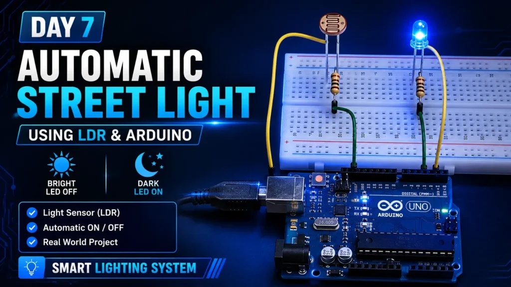
In this project, an LDR (Light Dependent Resistor) constantly measures the surrounding light intensity. The Arduino reads the sensor value through an analog input and automatically controls an LED based on the ambient light level.
When the environment becomes dark, the Arduino turns the LED ON to simulate a street light. As soon as enough light is detected, the LED automatically turns OFF, saving energy.
This project teaches Light Dependent Resistor (LDR), Analog Input Reading, Voltage Divider Circuit, Conditional Statements (if-else), and Automatic Light Control.
By finishing this project, you’ll know how sensors work with microcontrollers to automate real-world systems like street lights, garden lights, and smart home lighting.
Components Required
To build this circuit, collect these specific items from your kit:
Arduino Uno × 1, Breadboard × 1, LDR (Light Dependent Resistor) × 1, LED × 1, 10kΩ Resistor × 1, 220Ω Resistor × 1, Jumper Wires × 6, USB Cable × 1
Circuit Connections
Step 1: Connect Ground Rail
Connect the Arduino GND pin to the negative rail of the breadboard. This creates a shared ground connection for your entire circuit.
Step 2: Connect the LED
Put the LED into the breadboard. Connect the long leg (Anode) to Arduino Pin 7 through a 220Ω resistor. Connect the short leg (Cathode) to the breadboard GND rail.
Step 3: Connect the LDR
Put the LDR into the breadboard. Connect one leg of the LDR to Arduino 5V. Connect the other leg of the LDR to Arduino A0.
Step 4: Connect the 10kΩ Resistor
Create a voltage divider by connecting one end of the 10kΩ resistor to Arduino A0. Connect the other end to the breadboard GND rail.
Step 5: Verify Connections
Check all wiring before you power up the circuit. Make sure the LED direction is correct and verify that the LDR and resistor form a proper voltage divider.
Important: The LDR and 10kΩ resistor work together as a voltage divider. This allows Arduino to measure changing light levels through the analog input pin.
How the Arduino Code Works
Read Light Intensity
Arduino constantly reads the voltage from the LDR using the analogRead() function on A0. The measured value ranges from 0 to 1023, depending on the surrounding light intensity.
Compare with Threshold
The measured value is compared with a predefined threshold. If the light level falls below the threshold, Arduino knows that the environment is dark.
Control the LED
When darkness is detected, Arduino turns the LED ON. When enough light is available, Arduino turns the LED OFF.
Continuous Monitoring
The entire process repeats continuously inside the loop() function, allowing the system to respond instantly to changes in ambient light.
Expected Output
After uploading your code, here is what happens.
In bright light, the LED remains OFF. Covering the LDR or reducing the surrounding light turns the LED ON. Removing the cover or increasing the light turns the LED OFF again. The process repeats automatically without any user interaction.
Operational Troubleshooting
LED Does Not Turn ON :- Check the LED direction, resistor connections, and verify that the threshold value matches your lighting conditions.
LED Always Stays ON or OFF :- Adjust the threshold value in your code after observing the readings in the Serial Monitor.
LDR Values Do Not Change :- Verify that the LDR and 10kΩ resistor are connected correctly as a voltage divider.
Upload Errors :- Make sure the correct Arduino board and COM port are selected in the Arduino IDE.
What You Learned
By finishing this project, you now know :-
How an LDR sensor works, how to read analog sensor values, how voltage divider circuits operate, how to use analogRead(), and how to build an automatic lighting system using Arduino.
Next Lesson
In Day 8, you’ll learn how to use a Buzzer with Arduino to generate different sounds and simple melodies using digital outputs.