Arduino Code
Day 1 Core Training Documentation
Project Overview
The Blinking LED project is your starting point for learning microcontrollers. In this guide, an LED on Pin13 turns on and off between HIGH (+5V) and LOW (0V) every 1 second repeatedly.
This basic lesson teaches you core embedded hardware ideas:
Digital Outputs: Sending simple voltage signals from microcontroller pins. Arduino Programming Structure: Learning the setup section and the main loop. Breadboard Wiring: Making safe temporary electrical connections. Using Resistors with LEDs: Keeping components safe from too much current.
Components Required
To build this circuit, collect these specific items from your kit:
Arduino Uno MCU Board × 1 Solderless Prototyping Breadboard × 1 5mm Bright LED × 1 220Ω Current-Limiting Resistor × 1 Solid-Core Jumper Wires × 2 Type-B USB Cable × 1
Circuit Connections
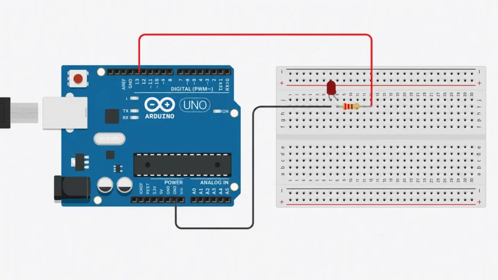
Step 1: Connect Ground Rail
Connect a jumper wire from an Arduino GND pin to the long negative rail (-) on your breadboard. This makes a shared ground for your whole circuit.
Step 2: Connect the LED
Place your LED legs in two different rows on the breadboard. Connect the long leg Anode (+) to Arduino Pin 13 through your 220Ω resistor. Connect the short leg Cathode (-) directly to the negative ground rail.
Step 3: Verify Connections
Check all wires before turning on the board. Your finished circuit should let the Arduino safely send voltage to Pin 13.
Polarity Warning: LEDs only let current go one way! Make sure your LED faces the right direction. Flipping the LED legs will stop current, so it won’t turn on.
How the Arduino Code Works
Configure the Output Pin
In the setup() section, tell the Arduino Pin 13 is an output. This lowers resistance, letting the board send voltage down the wire lines.
Turn the LED ON & OFF
Using digitalWrite(13, HIGH) sends full +5V voltage to the LED, making it light up fast. Using digitalWrite(13, LOW) cuts the voltage, dropping it to 0V (GND) and turning the LED off.
Create the Blink Effect
The delay(1000) command stops the program for exactly 1000 milliseconds between changes. Running these steps over and over in the loop() creates the blinking effect.
Expected Output
After you finish and upload the code to your board:
The LED turns ON for 1 second. The LED turns OFF for 1 second. This happens over and over on its own.
Operational Troubleshooting
LED Does Not Turn ON: If the light stays dark, check your wire connections. Look at LED direction, resistor placement, and jumper wires. Most problems happen because LED legs go in backwards.
Upload Failed Errors: If you get error messages, check your Arduino IDE settings. Make sure your USB cable can send data, pick the right board in Tools, and check the right COM port is chosen.
LED Stays ON Constantly: If your light never blinks and stays on all the time, look at your code. Make sure you uploaded the right blinking code and check that delay() is there between your on and off commands.
What You Learned
By finishing your first hardware project, you now know:
How to connect an LED to a microcontroller. How digital outputs switch power on and off. How to use hardware pins like Pin 13. How the main program runs loops in order.
Next Lesson
In Day 2, you will learn how to use digital inputs by adding a push button to your breadboard, using your button clicks to control your LED in real-time!
WHAT'S NEXT?
Ready to Build More?
Explore more Lifetronix projects, improve your skills, and turn your ideas into real working prototypes.