Arduino Code
Day 5 Core Training Documentation
Project Overview
The RGB LED Color Mixing project teaches you one of the most exciting ideas in electronics: making many colors using just one LED.
A standard LED can only make one color, but an RGB LED has three individual LEDs inside one package. It has Red, Green, and Blue.
By controlling how bright each color channel is using PWM (Pulse Width Modulation), Arduino can mix these colors together to create many different colors.
This project teaches you RGB Color Mixing, Pulse Width Modulation (PWM), Multiple Output Control, Analog Brightness Adjustment, and Color Generation Techniques.
By the end of this project, you’ll know how displays, LEDs, and smart lighting systems make millions of colors.
Components Required
To build this circuit, collect these specific items from your kit:
Arduino Uno × 1, Breadboard × 1, RGB LED × 1, 220Ω Resistor × 3, Jumper Wires × 4, USB Cable × 1
Circuit Connections
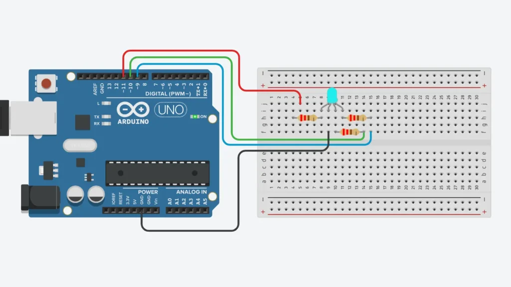
Step 1: Connect Ground Rail
Connect the Arduino GND pin to the negative rail of the breadboard. This gives the RGB LED a shared ground reference.
Step 2: Place the RGB LED
Put the RGB LED into the breadboard. Make sure all four legs go into separate rows.
Step 3: Connect the Red Channel
Connect the Red pin of the RGB LED to Arduino Pin 9 through a 220Ω resistor.
Step 4: Connect the Green Channel
Connect the Green pin of the RGB LED to Arduino Pin 10 through a 220Ω resistor.
Step 5: Connect the Blue Channel
Connect the Blue pin of the RGB LED to Arduino Pin 11 through a 220Ω resistor.
Step 6: Connect the Common Pin
Connect the longest leg (Common Cathode) of the RGB LED directly to the breadboard ground rail.
Step 7: Verify Connections
Check all resistor connections and make sure the RGB LED pins connect to the correct Arduino pins.
Important: This project uses a Common Cathode RGB LED. If you use a Common Anode RGB LED, you need to change your code logic.
How the Arduino Code Works
Configure the Output Pin
In setup(), Arduino sets Pin 9, Pin 10, and Pin 11 as output pins. Each pin controls one color channel of the RGB LED.
Generate Individual Colors
Using analogWrite(), Arduino controls the brightness of the Red Channel, Green Channel, and Blue Channel. Each channel takes PWM values between 0 and 255.
Create Color Mixing
Different combinations of Red, Green, and Blue make different colors. Red plus Green makes Yellow. Red plus Blue makes Purple. Green plus Blue makes Cyan. Red plus Green plus Blue makes White.
Control Brightness
PWM lets Arduino control how bright each color channel is. By changing brightness levels, you can make millions of unique color combinations.
Expected Output
After you finish and upload the code to your board:
The RGB LED displays Red, then Green, then Blue, then Yellow, then Purple, then Cyan, then White. The sequence repeats continuously.
Operational Troubleshooting
RGB LED Does Not Light Up: Check the common pin connection and verify LED direction.
Incorrect Colors Appear: Check the Red, Green, and Blue pin wiring. Some RGB LEDs use a different pin order.
Only One Color Works: Check all resistor connections and PWM pin assignments.
Upload Errors: Make sure the correct board and COM port are selected in Arduino IDE.
What You Learned
By finishing this project, you now know :-
How RGB LEDs work, how PWM controls LED brightness, how color mixing works, how to control multiple outputs at the same time, and how modern lighting systems make colors.
Next Lesson
In Day 6, you’ll build an Arduino Traffic Light System and learn how multiple LEDs can be controlled using timing logic and sequencing techniques.
WHAT'S NEXT?
Ready to Build More?
Explore more Lifetronix projects, improve your skills, and turn your ideas into real working prototypes.