Arduino Code
Day 3 Core Training Documentation
Project Overview
The Button Toggle LED project teaches one of the most important programming ideas in embedded systems: State Memory.
Unlike the last lesson where the LED only stayed ON while you pressed the button, this project lets Arduino remember the LED’s current state.
Press the button once and the LED turns ON. Press it again and the LED turns OFF.
This project teaches:
- State Management: Saving and remembering past states.
- Button Debouncing Concepts: Stopping unwanted extra triggers.
- Digital Inputs: Reading user actions through a button.
- Toggle Logic: Switching between ON and OFF states.
By the end of this lesson, you’ll know how Arduino can remember information and make choices based on what happened before.
Components Required
To build this circuit, collect these specific items from your kit:
Arduino Uno MCU Board × 1, Solderless Prototyping Breadboard × 1, Tactile Push Button × 1, 5mm Red LED × 1, 220Ω Current-Limiting Resistor × 1, Solid-Core Jumper Wires × 4, Type-B USB Cable × 1
Circuit Connections
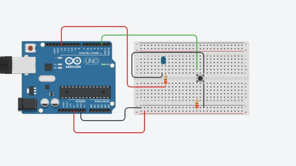
Step 1: Connect Ground Rail
Connect an Arduino GND pin to the negative rail (-) on the breadboard. This sets up a shared electrical reference for your circuit.
Step 2: Connect the LED
Put the LED on the breadboard. Connect the long leg Anode (+) to Arduino Pin 13 through a 220Ω resistor. Connect the short leg Cathode (-) to the negative rail.
Step 3: Connect the Push Button
Place the button across the middle gap on the breadboard. Connect one side of the button to Arduino Pin 2. Connect the other side directly to the ground rail.
Arduino will use its built-in pull-up resistor to watch for button presses.
Step 4: Verify Connections
Check LED connects to Pin 13. Check button connects to Pin 2. Check all ground wires are connected.
Pro Tip: If the LED changes state multiple times from one press, add a short pause delay in your code.
How the Arduino Code Works
Configure the Hardware
In setup():
Pin 13 is set as OUTPUT. Pin 2 is set using INPUT_PULLUP.
This lets Arduino safely watch the button while controlling the LED.
Detect a Button Press
Arduino keeps checking the button state using digitalRead().
When it finds a button press, the program makes a state change.
Store the LED State
A variable remembers if the LED is ON or OFF. Every button press flips the stored value.
Example: OFF → ON, ON → OFF
Toggle the LED
Based on the stored state:
LED State = ON → Pin 13 becomes HIGH, LED State = OFF → Pin 13 becomes LOW.
This creates the ON/OFF switch behavior.
Expected Output
After uploading your code:
Press the button once → LED turns ON. Release the button → LED stays ON. Press the button again → LED turns OFF. Release the button → LED stays OFF.
Every button press continues the cycle.
Operational Troubleshooting
LED Does Not Toggle: Check that the button connects to Pin 2 and GND. Wrong button placement is the most common problem.
LED Toggles Multiple Times: This happens because of button bounce. Add a pause delay or use better button checking logic.
LED Never Turns OFF: Look at your toggle variable and make sure it changes after every button press.
Upload Errors: Check the board, COM port, and USB cable in Arduino IDE.
What You Learned
By finishing this project, you now know:
How to build a real ON/OFF switch using Arduino. How state variables save information. How Arduino remembers past events. How to write toggle code. The basics of interactive embedded systems.
Next Lesson
In Day 4, you’ll learn how to control LED brightness using PWM (Pulse Width Modulation), letting Arduino make smooth fading effects instead of just ON and OFF states.
WHAT'S NEXT?
Ready to Build More?
Explore more Lifetronix projects, improve your skills, and turn your ideas into real working prototypes.