
Get Full Source Code
Purchase and download the complete source code for this project.
🛒 Get Source CodeWHAT'S NEXT?
Ready to Build More?
Explore more Lifetronix projects, improve your skills, and turn your ideas into real working prototypes.
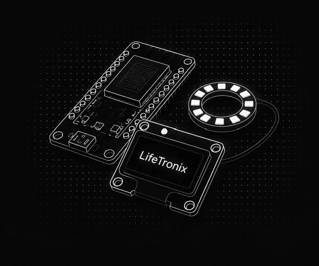
ESP32 Mini Computer LIFE OS Project Documentation
Project Overview
The ESP32 Mini Computer LIFE OS turns an ESP32 and a 128×64 SSD1306 OLED display into a tiny computer-like system with its own custom operating-system-style interface, complete with apps, games, and utilities.
The ESP32 drives the OLED over I2C, manages a password-protected LIFE OS interface with a calculator, notes, timer, clock, and games, and also hosts its own mobile-friendly web dashboard so the whole system can be controlled from a phone browser.
Key Features: LIFE OS provides a password-protected interface with a calculator, notes app, timer, clock, Snake and Dino games, Wi-Fi connectivity, a mobile web dashboard, system information, and adjustable display settings.
Components Required
To build this project, collect these specific items from your kit and assemble them in a proper working environment.
You will need one ESP32 Development Board, one SSD1306 OLED Display (128×64), push buttons as required, one Breadboard, jumper wires as required, and one USB Cable.
Circuit Connections
Step 1: Connect OLED Power to ESP32
Connect the OLED display’s VCC pin to the ESP32’s 3.3V output and the OLED’s GND pin to the ESP32’s GND, giving the display a stable power source.
Step 2: Connect the SDA Linex
Connect the OLED display’s SDA pin to GPIO 21 on the ESP32, forming the data line of the I2C connection used to drive the display.
Step 3: Connect the SCL Line
Connect the OLED display’s SCL pin to GPIO 22 on the ESP32, forming the clock line of the I2C connection alongside the SDA wire.
Step 4: Verify All Connections Before Uploading Code
Double-check the SDA and SCL wiring, confirm the OLED’s I2C address, and test button continuity with a multimeter before powering on the ESP32.
The OLED display communicates over I2C using SDA on GPIO 21 and SCL on GPIO 22, with a default address of 0x3C. Always confirm this address and check wiring before uploading the code.
Software Requirements
Before uploading code to your ESP32, install the following software components, libraries, and drivers on your development system.
Arduino IDE : Download latest version from Arduino website. Required for writing and uploading code to ESP8266 microcontroller.
ESP8266 Board Package : Add via Boards Manager with “esp8266 by ESP8266 Community” package version 2.7.0 or higher.
ESP8266WiFi Library : Included with board package. Provides WiFi.scanNetworks(), WiFi.softAP(), and WiFi.begin() functions for WiFi operations.
DNSServer Library : Included with board package. Enables DNS spoofing on port 53 redirecting all DNS requests to 192.168.4.1 for captive portal.
ESP8266WebServer : Library: Included with board package. Hosts HTTP server on port 80 serving captive portal login interface and control pages.
CH340 USB Driver : Download for your operating system. Enables USB serial communication between computer and ESP8266 board.
How the Project Code Works
Initialize WiFi Dual Mode and DNS Server
The setup() function calls WiFi.mode(WIFI_AP_STA) enabling access point broadcast and station connection simultaneously. DNS server starts on port 53 at IP 192.168.4.1 redirecting all DNS queries to the evil twin.
Scan Networks and Store BSSID Information
performScan() function calls WiFi.scanNetworks() detecting nearby networks. For each detected network, SSID, BSSID (MAC address), and channel number store in _Network struct array. Updates every 15 seconds enabling target selection.
Create Fake Access Point with Target SSID
When user selects target network, WiFi.softAP(_selectedNetwork.ssid.c_str()) creates fake network with identical SSID name. DNS server intercepts all requests redirecting browsers to captive portal login page.
Process Password Verification Against Real Network
When user enters password, code calls WiFi.begin(_selectedNetwork.ssid.c_str(), password, channel, BSSID) attempting connection to real target network. Success indicates correct password. Timeout means password is wrong.
Serve Captive Portal and Control Interface
webServer handles HTTP requests on port 80. handleIndex() serves HTML captive portal page. handleResult() displays password verification results. handleAdmin() provides control dashboard for network management.
Expected Output
After uploading code and opening Serial Monitor at 115200 baud, observe startup messages and network scanning beginning.
Serial Monitor displays detected WiFi networks with SSID, BSSID, channel, and signal strength. Web interface at 192.168.4.1 shows network list with Select buttons and options to start/stop evil twin mode. Successfully captured passwords display confirmation messages.
Operational Troubleshooting
ESP8266 Does Not Detect WiFi Networks or Shows Empty Scan Results :- Verify WiFi.mode(WIFI_AP_STA) is correctly called in setup() function. Check that wifi_promiscuous_enable(1) enabled packet capture mode. Restart ESP8266 with reset button. Verify antenna connection and WiFi module functioning properly.
Captive Portal Does Not Load or Connections Do Not Redirect to Login Page :- Confirm DNSServer.start(53, “*”, apIP) is running correctly in setup(). Verify DNS port 53 is not blocked by firewall software. Check that DNS redirects all queries to 192.168.4.1 access point IP. Open browser and manually visit 192.168.4.1:80.
Password Verification Does Not Work or Shows Wrong Results Constantly :- Verify correct BSSID stored in _selectedNetwork.bssid before attempting WiFi.begin(). Check that channel number matches target network exactly. Confirm WiFi credentials in code match actual network SSID and password format. Test connection manually on device.
What You Learned
By finishing this project, you understand how WiFi networks operate at the MAC and application layers including SSID broadcasting, BSSID identification, and channel management. You learned how access points can be spoofed, how DNS spoofing redirects traffic, and how captive portals capture credentials in security research.
You can apply these concepts to secure wireless networks by understanding attack vectors and implementing proper authentication (WPA3), certificate validation, and intrusion detection systems. You experienced that WiFi security requires multiple defense layers making it difficult to compromise properly secured networks in authorized testing environments.