Arduino Code
Day 4 Core Training Documentation
Welcome to Day 4 of your core electronics training! In the past lessons, your microcontroller only did two things: an LED was either completely ON or completely OFF. Today, we go beyond those simple digital states and learn how to control an LED’s brightness smoothly, creating a professional fading or breathing effect.
Project Overview
The PWM LED Brightness Control project teaches you one of the most important ideas in embedded engineering: Pulse Width Modulation (PWM). Instead of changing the actual voltage output, the Arduino switches a digital pin between HIGH and LOW states very fast. By changing how long the signal stays HIGH compared to LOW, we control how much power goes to the LED.
Pulse Width Modulation (PWM) lets you simulate analog voltage levels using fast digital switching. Analog Output Simulation uses analogWrite() to map digital values into smooth power changes. Iterative Logic Structures uses for loops to scale values smoothly over time. Variable-Based Control connects hardware output pins to dynamic programming variables.
Components Required
To build this circuit, collect these specific items from your kit:
Arduino Uno × 1 is your main microprocessing unit. Breadboard × 1 is your solderless prototyping workspace. LED (Any Color) × 1 is your visual output. 220Ω Resistor × 1 protects the LED from too much current. Jumper Wires × 2 connect your components together. USB Cable × 1 provides power and transfers your code.
Circuit Connections
Follow these steps carefully to build your hardware on the breadboard.
Step 1: Establish the Common Ground
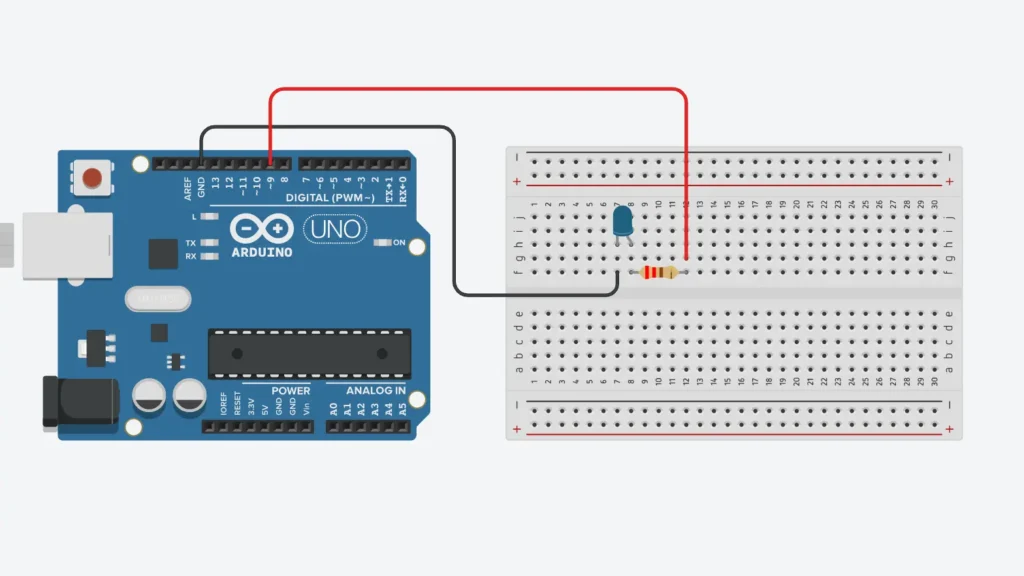
Connect a jumper wire from the GND pin on your Arduino to the negative (-) rail of your breadboard. This creates a shared ground plane for your circuit.
Step 2: Wire the LED Array
Put your LED pins into separate rows on the breadboard. The long leg (Anode / +) connects to Digital Pin 9 on the Arduino through your 220Ω resistor. The short leg (Cathode / -) connects directly to your negative breadboard ground rail.
Step 3: Pre-Power Inspection
Check your LED direction and make sure your resistor legs aren’t crossing other tracks before you connect your USB cable.
Critical Hardware Note: PWM signals can only come from certain digital pins. On the Arduino Uno, PWM only works on pins marked with a tilde symbol (~): Pin 3, 5, 6, 9, 10, and 11.
How the Arduino Code Works
Configure the Output Pin
In setup(), Arduino sets Pin 9 as an output. This tells the board to prepare the pin to send power to the LED.
The Fade-In Phase
The first for loop slowly increases the brightness value from 0 to 255. As the value goes up, more power goes to the LED, making it grow brighter step by step.
The Fade-Out Phase
The second for loop does the opposite. It slowly decreases the value from 255 down to 0. As the number gets smaller, less power reaches the LED, making it dim smoothly.
Managing 8-Bit PWM Resolutions
The analogWrite() command sends a number to the Arduino’s timer registers. This gives you control from 0 to 255. A value of 0 means 0% duty cycle and the LED is completely OFF. A value of 128 means 50% duty cycle and the LED glows at about half brightness. A value of 255 means 100% duty cycle and the LED is at full brightness.
Expected Output
After uploading your code to the board, you will see this behavior.
The LED will fade smoothly from completely OFF up to its brightest point. Once it reaches the peak, it will fade back down to OFF. This process repeats continuously, creating a smooth breathing lighting effect.
Operational Troubleshooting
LED Switches ON/OFF Abruptly (No Fading): Check your Pin Assignment. Make sure your wire goes to Pin 9. Standard pins cannot do PWM and will just turn fully ON or fully OFF.
LED Remains Completely Dead: Check LED Polarity. Unplug your USB cable, turn your LED 180 degrees to flip it around, put it back in, and look for broken connections.
Fading Changes Are Not Smooth: Check Loop Timing. Look at the delay() values in your code. Smaller delays make the fading faster, while larger delays make it slower.
Arduino IDE Upload Errors: Check Port and Board. Open the Tools menu in your IDE to make sure you have Arduino Uno selected and an active COM port chosen.
What You Learned
The Physics of Pulse Width Modulation teaches you how to control electrical current using fast switching duty cycles. Deploying 8-Bit Controllers shows you how to use hardware registers from 0 to 255. Symmetrical Program Flows teaches you how to use loops that go up and down in your code.
Next Lesson
In Day 5, we take this PWM system and use it with an RGB LED module, learning how to control individual color values to make thousands of custom colors from one LED!
WHAT'S NEXT?
Ready to Build More?
Explore more Lifetronix projects, improve your skills, and turn your ideas into real working prototypes.