Arduino Code
Day 6 Core Training Documentation
Project Overview
The Traffic Light System project teaches you one of the most common real-world uses of embedded systems and automation.
In this project, Arduino controls three LEDs that look like a real traffic signal. The Red LED means Stop. The Yellow LED means Wait. The Green LED means Go.
Using digital outputs and timing logic, Arduino automatically switches between different traffic light states, creating a realistic traffic signal sequence.
This project teaches Multiple Output Control, Timing and Delays, Sequential Programming, Automation Systems, and Real-World Traffic Signal Logic.
By finishing this project, you’ll know how microcontrollers can automate tasks and control multiple devices in a specific sequence.
Components Required
To build this circuit, collect these specific items from your kit:
Arduino Uno × 1, Breadboard × 1, Red LED × 1, Yellow LED × 1, Green LED × 1, 220Ω Resistor × 3, Jumper Wires × 6, USB Cable × 1
Circuit Connections
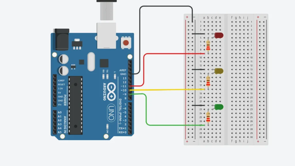
Step 1: Connect Ground Rail
Connect the Arduino GND pin to the negative rail of the breadboard. This creates a shared ground connection for all LEDs.
Step 2: Connect the Red LED
Put the Red LED into the breadboard. Connect the long leg (Anode) to Arduino Pin 8 through a 220Ω resistor. Connect the short leg (Cathode) to the breadboard GND rail.
Step 3: Connect the Yellow LED
Put the Yellow LED into the breadboard. Connect the long leg (Anode) to Arduino Pin 9 through a 220Ω resistor. Connect the short leg (Cathode) to the breadboard GND rail.
Step 4: Connect the Green LED
Put the Green LED into the breadboard. Connect the long leg (Anode) to Arduino Pin 10 through a 220Ω resistor. Connect the short leg (Cathode) to the breadboard GND rail.
Step 5: Verify Connections
Check all LED directions and resistor placements before you power up the circuit.
Important: Every LED must have its own 220Ω current-limiting resistor to stay safe.
How the Arduino Code Works
Configure the Output Pin
In setup(), Arduino sets Pin 8, Pin 9, and Pin 10 as output pins. These pins control the Red, Yellow, and Green LEDs.
Stop State
The Red LED turns ON while the Yellow and Green LEDs stay OFF. This is the STOP signal.
Ready State
The Red and Yellow LEDs turn ON together. This means the signal is about to change.
Go State
The Green LED turns ON while the Red and Yellow LEDs turn OFF. This is the GO signal.
Warning State
The sequence repeats inside the loop() function, creating a complete traffic light system.
Repeat the Cycle
The sequence repeats inside the loop() function, creating a complete traffic light system.
Expected Output
After uploading your code, here is what happens:
Red LED turns ON for 5 seconds. Red and Yellow LEDs turn ON together for 2 seconds. Green LED turns ON for 5 seconds. Yellow LED turns ON for 2 seconds. The sequence repeats continuously.
The circuit works like a real traffic signal.
Operational Troubleshooting
One LED Does Not Turn ON :- Check the LED direction and verify the resistor connection.
Incorrect Sequence :- Make sure each LED connects to the correct Arduino pin.
All LEDs Stay ON :- Check your uploaded code and confirm the pin numbers match your wiring.
Upload Errors :- Verify the correct board and COM port are selected in Arduino IDE.
What You Learned
By finishing this project, you now know :-
How to control multiple LEDs at the same time, how timing logic works using delay(), how automation systems operate, how to create sequential output patterns, and how real-world traffic lights are controlled.
Next Lesson
In Day 7, you’ll learn how to use a Buzzer with Arduino to generate sounds and simple melodies.
WHAT'S NEXT?
Ready to Build More?
Explore more Lifetronix projects, improve your skills, and turn your ideas into real working prototypes.