Arduino Code
Day 2 Core Training Documentation
Project Overview
The Button Controlled LED project teaches you a key idea in embedded systems: Digital Inputs. In this guide, a push button on Pin 2 is watched to control an LED on Pin 13.
When you press the button, the Arduino notices a voltage change and turns the LED ON. When you let go, the connection breaks and the LED turns OFF.
This lesson covers several important hardware and programming ideas:
Digital Inputs: Reading simple logic signals from outside interactive parts. Push Button Interfacing: Connecting push buttons to a microcontroller input line. Input/Output Interaction: Writing code to change physical outputs based on what the user does. Serial Monitoring: Sending real-time hardware numbers back to your computer screen.
Components Required
To build this circuit, get these specific items from your kit:
Arduino Uno MCU Board × 1 Solderless Prototyping Breadboard × 1 5mm Bright LED × 1 Tactile Push Button Switch × 1 220Ω Current-Limiting Resistor × 1 Solid-Core Jumper Wires × 4 Type-B USB Cable × 1
Circuit Connections
Step 1: Establish the Common Ground
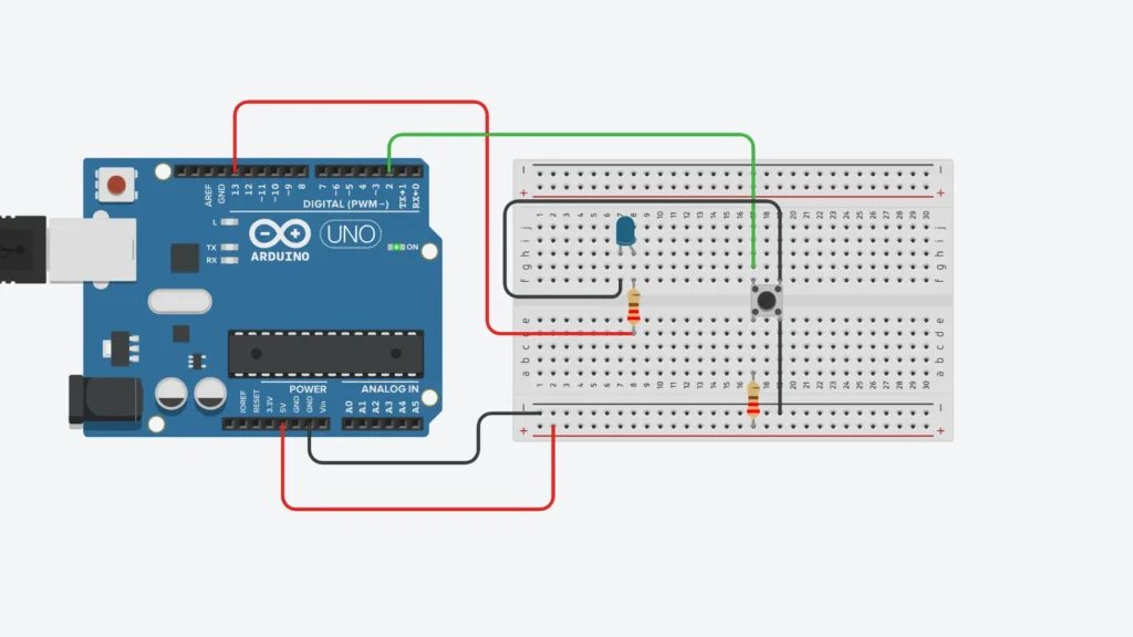
Connect a jumper wire from an Arduino GND pin to the long blue negative rail (-) on your breadboard. This creates a shared voltage reference for your circuit.
Step 2: Wire the LED Output Channel
Put your LED in two different breadboard rows. Connect the long leg Anode (+) to Arduino Pin 13 through your 220Ω resistor. Connect the short leg Cathode (-) directly to the negative ground rail.
Step 3: Integrate the Push Button
Place the push button across the middle separation trench on your breadboard. Connect one button pin directly to Arduino Pin 2. Connect the opposite button pin to the negative ground rail.
Push Button Warning: Always place the push button across the middle split trench. Wrong placement on one row can connect both terminals together permanently, breaking the circuit and stopping the microcontroller from seeing changes.
Step 4: Final Inspection
Check that your wires go to Pin 13 and Pin 2 cleanly, and make sure all ground wires connect back to the breadboard’s negative rail.
How the Arduino Code Works
Configure the Output Pin
In your setup() function, the Arduino sets the pin modes:
Pin 13 is set as OUTPUT to send power to the LED. Pin 2 is set using INPUT_PULLUP mode.
The built-in pull-up resistor pulls the voltage on Pin 2 to a default HIGH (+5V) when the button is open, so you don’t need an outside resistor.
Reading and Interpreting Hardware States
In your loop() function, the Arduino checks the button using digitalRead(2):
Button Pressed: The switch closes and connects to GND. Pin 2 goes to LOW (0V), telling the Arduino to turn the LED on. Button Released: The switch opens and breaks the path to ground. The pull-up brings the pin back to HIGH (+5V), telling the Arduino to turn the LED off.
Serial Monitor Feedback
The code also sends information back to the computer screen using Serial.println(). When the button is closed to ground, it prints a 1 to show the button is pressed. When you let go, it prints a 0.
Expected Output
After you finish and upload your code to the board:
Pressing the button down will turn on your LED instantly. Letting go of the button will turn the LED off instantly. Opening your Serial Monitor at 9600 baud will show a live stream of 1 when pressed and 0 when released.
Operational Troubleshooting
LED Does Not Turn ON: If the button click doesn’t turn on the light, check your output wires. Look at LED direction, make sure your resistor sits right on the correct lines, and check that your wire goes to Pin 13.
Push Button Not Responding: If your button clicks don’t do anything, check your button placement. Make sure the button crosses the middle gap correctly and that one side connects to GND while the other connects to Pin 2.
Serial Monitor Shows No Values: If your screen is blank, check your setup code. Make sure your code has Serial.begin(9600); in setup(), and check that the baud rate in your Serial Monitor window matches 9600.
LED Remains ON Continuously: If your LED is on before you touch the button, something is wrong with your circuit or code. Make sure you used INPUT_PULLUP in your setup() and not just INPUT.
What You Learned
By finishing your second microcontroller project, you now know:
How to wire and use a push button switch correctly. How an Arduino reads digital input signals. How to build code that connects outputs to user input. How INPUT_PULLUP makes circuits easier by using built-in chip resistors. How to use Serial Monitor to see and debug your code working.
Next Lesson
In Day 3, you will learn how to turn a simple push button into a real toggle! We will show how to save old states in software memory, where one click turns the LED on and the next click turns it off.
WHAT'S NEXT?
Ready to Build More?
Explore more Lifetronix projects, improve your skills, and turn your ideas into real working prototypes.